Precision Non-contact Measurement
Precision measurement is our focus. Our laser and ultrasonic-based technologies provide non-contact diameter measurements for a wide range of materials. Our accurate suite of tools cover outside diameter (OD), ovality (eccentricity), wall thickness (coating thickness/material thickness), concentricity, inside diameter (ID), and more.
To learn more about the operating principles of laser micrometers, ultrasonic material thickness measurement and laser profile measurement, visit these pages or contact us:
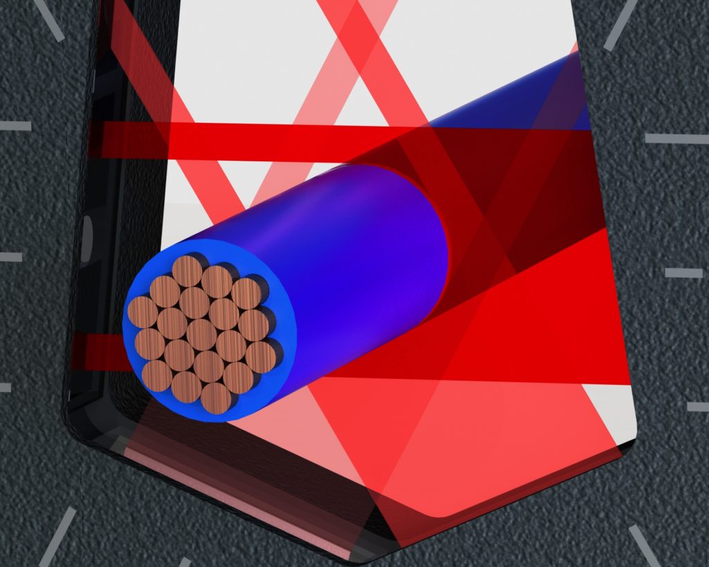
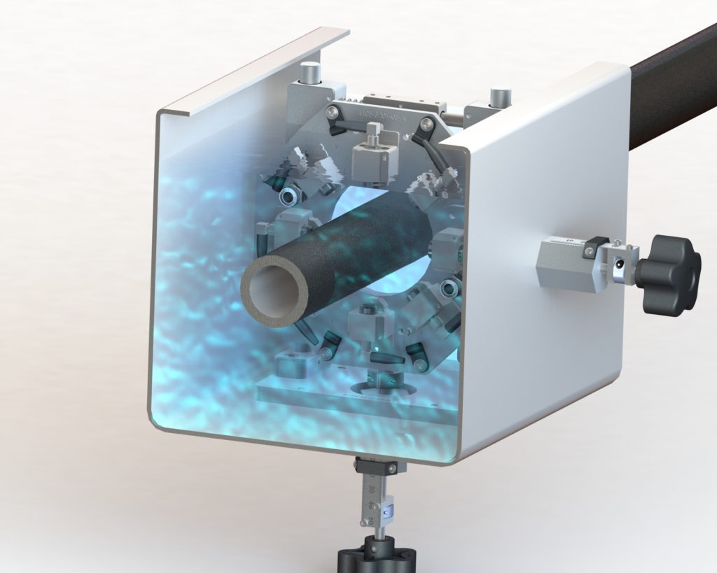
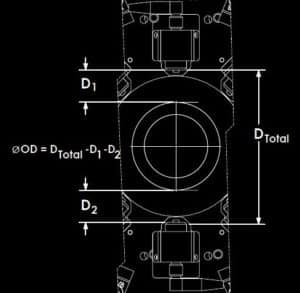
Triple-axis laser micrometers measure the outside diameter of a part from three directions. The three measurements are coplanar and are separated by 60 degrees from each other. The average of the three measurements is also calculated.
Triple-axis provides the best overall diameter measurement, more capable defect detection, and accurate ovality measurement regardless of orientation.
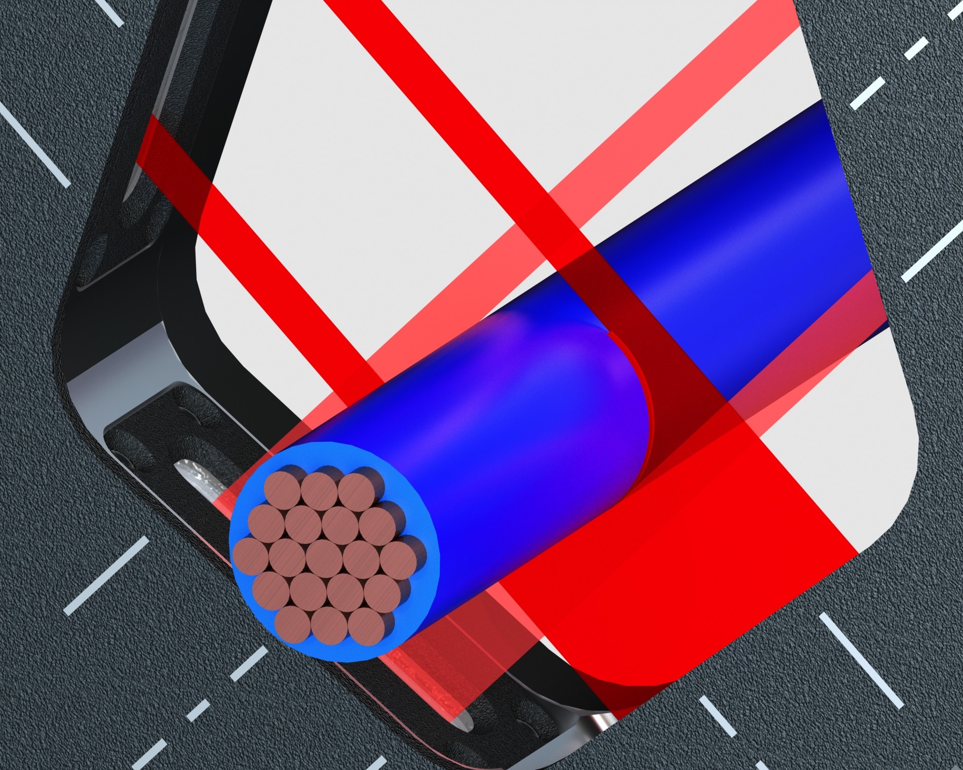
Dual-axis laser micrometers measure the outside diameter of a single part from two directions. The two measurements are coplanar and perpendicular to each other. The average of and difference between the two measurements are also calculated.
Dual-axis provides good average diameter, defect detection, and ovality measurement for many extruded products.
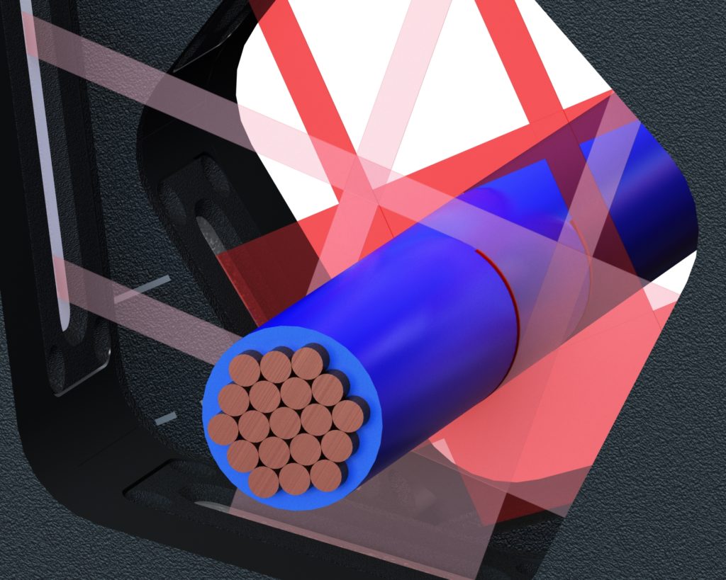
Four-axis laser micrometers measure the outside diameter of a part from four directions. This measurement is achieved with either four single-axis micrometers mounted to a common surface for coplanar measurement or using two dual-axis laser micrometers offset and rotated 45 degrees relative to each other. Note that with two dual-axis micrometers, the measurements from one micrometer are not coplanar with measurements from the other.

Six-axis laser micrometers measure the outside diameter of a part from six directions. This measurement is achieved using two Triton triple-axis laser micrometers offset and rotated 30 degrees relative to each other. Note that the measurements from one micrometer are not coplanar with measurements from the other.
Transparent or translucent
Measuring transparent or translucent materials can be challenging, as laser light from the micrometer can travel through the product and falsely detect additional parts. To avoid this, LaserLinc uses special processors and software to filter and ignore any false information resulting from laser light passing through the product being measured. The special software is included free with all LaserLinc processors and is switched on when needed by the user.

Multi-Strand
LaserLinc uses specialized hardware and software to identify each distinct strand and generate separate diameter measurements for each independent strand. The system also detects when strands are no longer present in the measurement area, and when this happens, the equipment identifies which strand(s) are missing and continues to measure those that remain.
All of LaserLinc’s single-, dual-, and triple-axis laser micrometers may be used in multi-strand diameter measurement applications.


Single-layer ultrasonic measurement is calculated using the following method:
A high-frequency sound wave is transmitted from the transducer toward the product to measure. As the sound wave strikes each surface, an echo is generated. The sound wave strikes the second surface just microseconds, or less, after hitting the first surface.
The time between the two echoes is directly proportional to the product’s thickness. In almost all applications, multiple transducers are positioned at either different angles or different locations for multiple thickness measurements.
Contact LaserLinc and speak with an applications engineer for help determining the best sensor assembly options for your application.
Tube, hose, pipe:

Composite Decking:
Two transducers underneath, two above. Measuring thickness of the outer layer. You can see that the profile has a thin skin all the way around it. With ultrasonics, we can measure that skin thickness.

A high-frequency sound wave is transmitted from the transducer toward the product to measure. Echoes are generated as the sound wave strikes the product’s surface, each interface between internal layers, and finally the surface of the inside of the product.
The time between consecutive echoes is directly proportional to the thickness of the layer. In almost all applications, multiple transducers are used, positioned at either different angles or different locations, for multiple thickness measurements.
Contact LaserLinc and speak with an applications engineer for help determining the best sensor assembly options for your application.

Material thickness is calculated as the difference between the position of the product’s top edge and the top edge of a reference mandrel.
For tube, hose, and small diameter pipe, the BenchLinc™ ID-OD-Wall system provides for automatic rotation of the sample to measure total wall thickness from multiple angles.

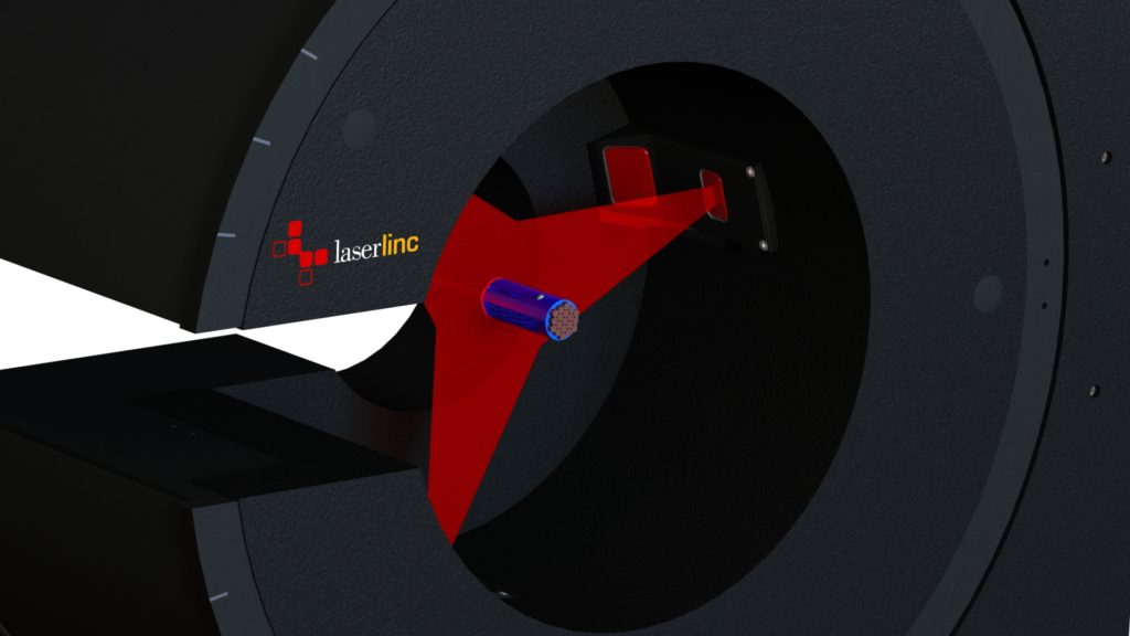
 Three or more sensors positioned around a central area provide 360° surface inspection. The product's surface is continuously checked for flaws. LaserLinc’s FlawSense technology offers a complete check of the product’s surface rather than just a few checks. There are no blind spots using a laser-line triangulation system, and since it isn’t shadow-based, pits and concave deformities can be detected that can’t be detected using a laser micrometer.

Single-axis laser micrometers measure the total range of space occupied by a part in the laser field over time. This includes the highest location of the top of a part to the lowest location of the bottom of the part as it moves through a cycle. (Note: requires software filtering to produce the measurement value.)
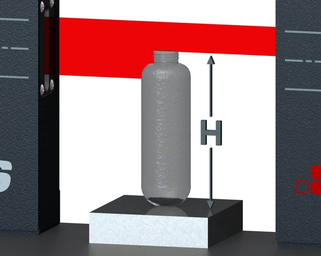
Single-axis laser micrometers measure the height of a part relative to a reference surface.
As the bottle rests on the reference surface, its height is calculated based on the edge position established by the top of the bottle. As the edge position moves higher or lower in the measurement field of the micrometer, the height measurement increases or decreases.
A section of rail for trains:

One end of the rail is positioned against a stop, the other breaks the plane of a single-axis gauge mounted vertically.
Like measuring height, measuring length is achieved by positioning one end of the part against a reference surface and using a laser micrometer to measure the other end position. The range of lengths that can be measured is nearly infinite. However, at any given physical position of the micrometer, the range of lengths measured is equal to the largest capacity of the micrometer. Measuring other lengths requires moving the reference surface or the micrometer.
Laser micrometers
Average coating thickness can be measured by calculating the difference in product diameter before and after a coating is applied. The diameter measurement at each location can be made using single, dual, or triple-axis laser micrometers. A triple-axis will provide the best average diameter measurement and a more accurate average coating thickness than using dual or single-axis laser micrometers.
This measurement can be performed in-process in certain applications, such as with insulating wire. In fact, in this application, using in-process diameter measurement before and after insulating the wire coupled with an UltraGauge ultrasonic wall thickness sensor provides the most accurate and reliable measurement solution.
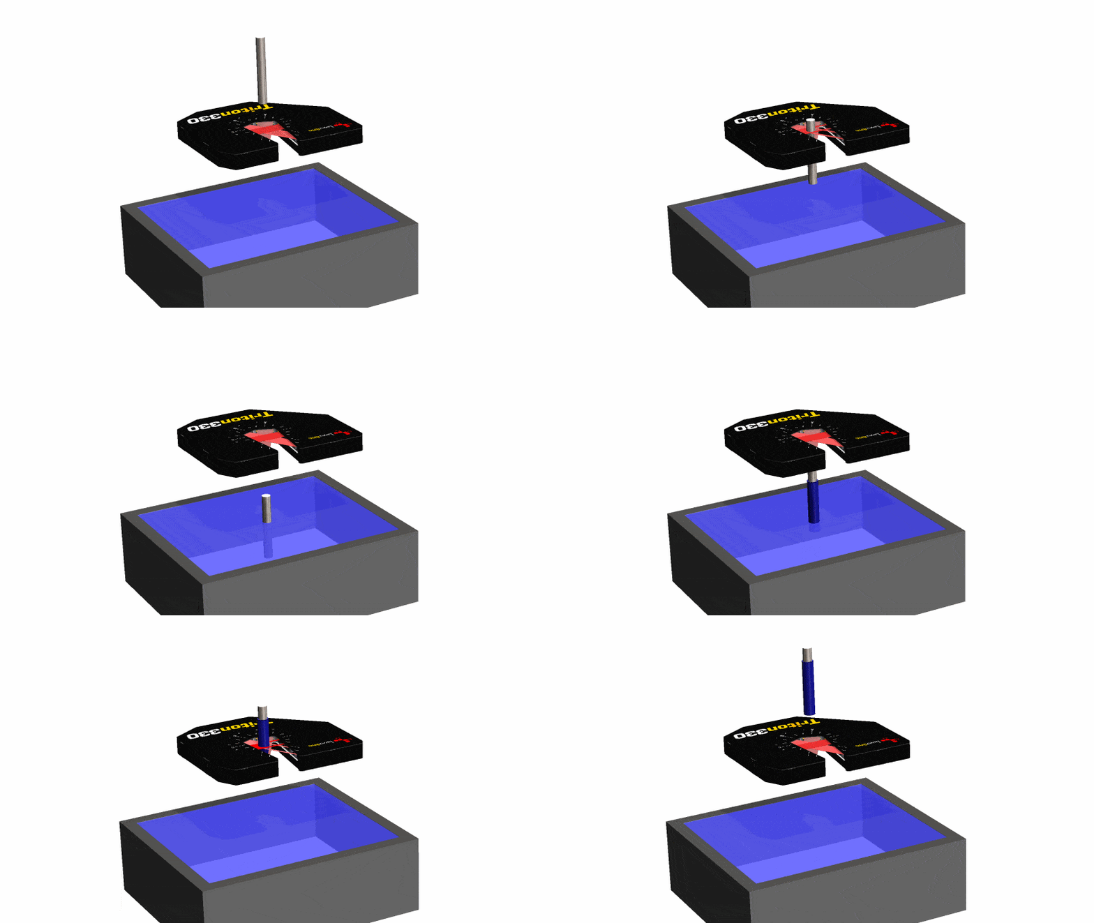
Off-line: Triple-axis laser micrometer
Average coating thickness can be measured by calculating the difference in product diameter before and after a coating is applied. Using a triple-axis laser micrometer provides the best average diameter measurement and provides a more accurate average coating thickness than using dual or single-axis laser micrometers.
In a dip-coating application, the diameter of a part is measured before a coating operation and then afterward.
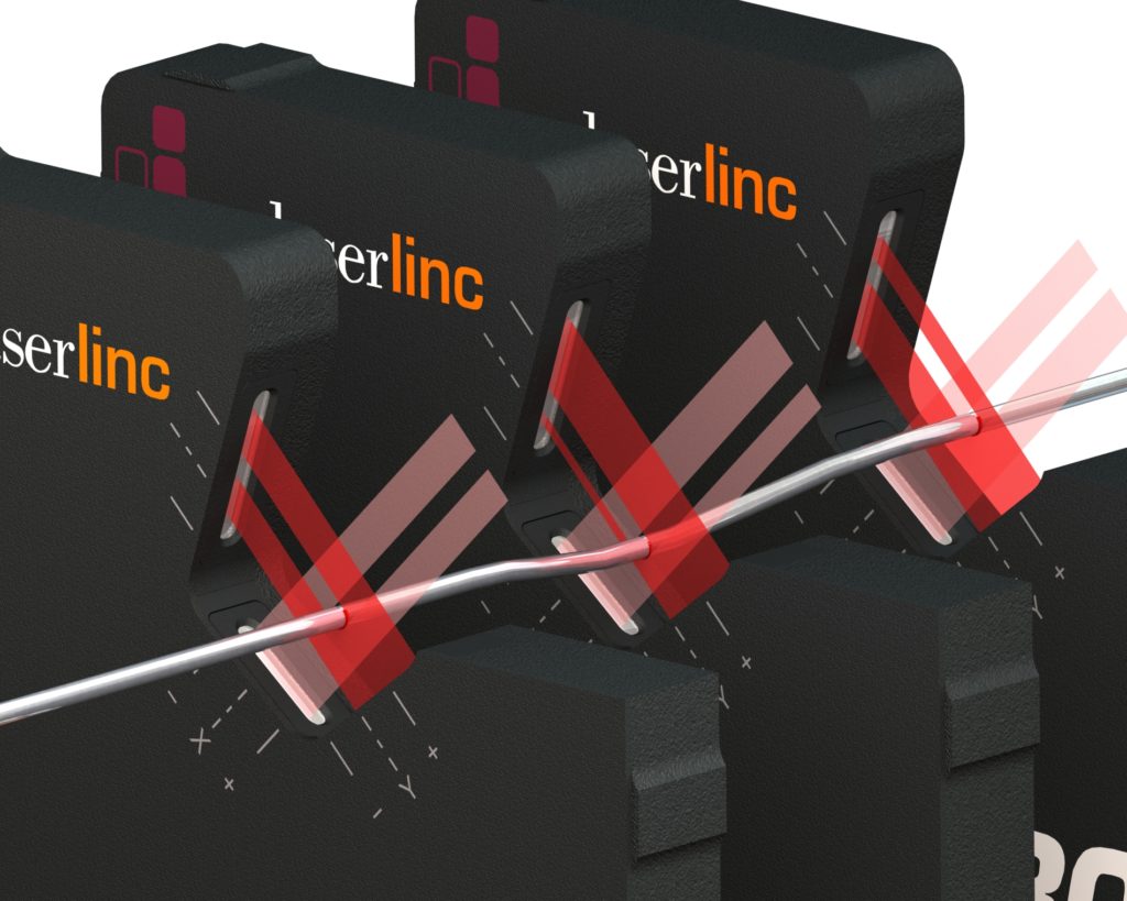
Dual-axis laser micrometers measure the straightness of a part by checking its position in three separate dual-axis laser micrometers. The part’s position in the first and last micrometers establishes a virtual straight line, or datum, through the center of the product. The micrometer in the middle measures the deviation of the part from that straight line. All three micrometers can also measure diameter at the same time.
Alternatively, the measurement can be made by continuous inspection of product position along the length of a part using LaserLinc’s Metron™ system or similar automated inspection system.

Triple-axis laser micrometers provide excellent precision in diameter measurement. Coupled with LaserLinc’s hardware integration of a length sensor (an encoder), the change in diameter of a part over a given length can be calculated precisely. The taper can be measured in each axis independently or based on the change in the average diameter.

Dual-axis laser micrometers provide excellent precision in diameter measurement. With two axes of measurement, this approach determines taper in each axis independently or based on the change in the average diameter.
This can be done in-process such as in the production of extruded medical tubing, or in the off-line QA measurement of a discrete product by using a LaserLinc Metron™ automated inspection system.

A single-axis laser micrometer measures diameter from one direction. An accurate taper measurement is obtained by moving the micrometer and product relative to each other, and simultaneously measuring diameter and the relative amount of movement.
This can be done in-process such as in the production of a centerless ground guide wire, or in the off-line QA measurement of a discrete product by using a LaserLinc Metron automated inspection system.
 Three or more cameras positioned around a central area provide a 360° product profile. A circle fit algorithm is applied to the set of points obtained from the cameras to calculate product diameter. By tracking product diameter as the product moves, taper is measured.
Profile technology offers a more comprehensive check of the product’s contour compared to a laser micrometer, and is therefore much less susceptible to measurement variation of products that aren’t round.

A single-axis laser micrometer is used to measure the movement of one edge of a part (top or bottom) as the part is rotated about its center. The part must rotate at least 360 degrees. The difference between the lowest and highest position of the monitored edge is the total indicated runout.
This measurement is also known as total indicator reading or full indicator movement.
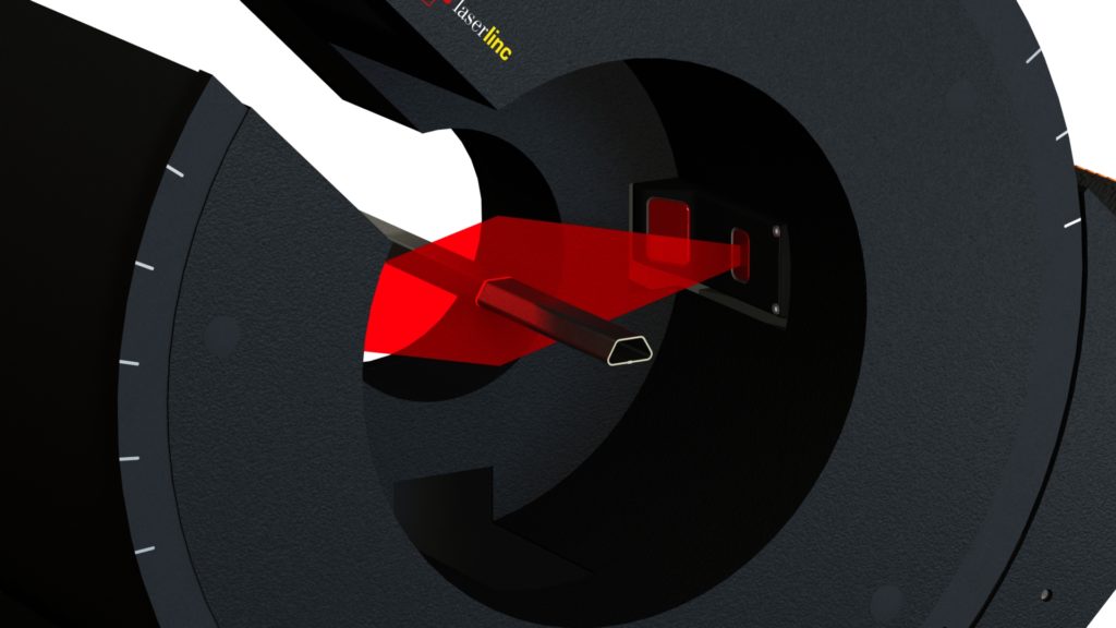

With a pair of cameras, one positioned on either side of the product to measure, each product side is mapped. Since each side of the product is mapped, several variations of a width measurement may be obtained: the maximum width, the minimum width, and average width.
With profile technology, the entire product is measured and the precision of the measurement is unaffected by twist in the product whereas a laser micrometer must be perpendicular to the product to make an accurate width measurement and it can only report maximum width.

Dual-axis laser micrometers simultaneously measure the width and height of a rectangular or similarly-shaped part. The part must be aligned with the laser field to make an accurate measurement.
Visit this page to learn how to ensure accurate measurement of rectangular or similarly-shaped products.
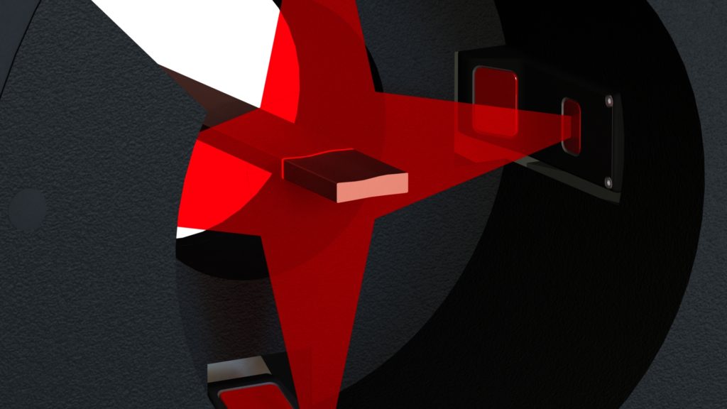

With four cameras positioned 90 degrees apart, each product side is mapped. Since each side of the product is mapped, several variations of width and height measurements may be obtained: the maximum, the minimum, and the average of each characteristic.
With profile technology, the entire product is measured and measurement precision is unaffected by product orientation, whereas a laser micrometer must be perpendicular to the product to make an accurate measurement and it can only report a maximum width and maximum height.

Three or more cameras positioned around a central area provide a 360° product profile. The result is a set of more than a thousand points per frame, or thousands of points when using high-resolution cameras. Within a selected region of interest, a best fit line can be calculated.
The angle between any pair of lines can be measured, and interior or exterior measurements are available.
Three or more cameras positioned around a central area provide a 360° product profile. The result is a set of more than a thousand points per frame, or thousands of points when using high-resolution cameras.
Within a selected region of interest encompassing a curved section of the product’s surface, an algorithm applied to the points in the selected region calculates the arc’s radius that best fits the data.

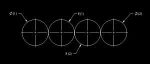
Three or more cameras positioned around a central area provide a 360° product profile. The result is a set of more than a thousand points per frame, or thousands of points when using high-resolution cameras.
An algorithm applied to the points calculates the area contained within the shape created by connecting the points.

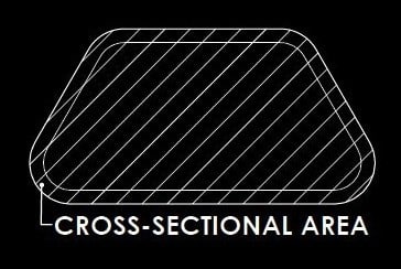
Three or more cameras positioned around a central area provide a 360° product profile. The result is a set of more than a thousand points with each frame, or thousands of points when using high-resolution cameras.
An algorithm applied to the points calculates the area contained within the shape created by connecting the points. By coupling the cross-sectional area obtained from each frame produced by the cameras with length information produced by an encoder tracking product movement, a Profile Vu system measures the product’s volume.


Three or more cameras positioned around a central area provide a 360° product profile. A set of more than a thousand points, several thousand with high-resolution devices, are obtained from the cameras each frame. Various algorithms are applied to regions of interest to calculate measurements such as diameter, radius, angle, distance, length, position, height and width.
In addition, the distance between two points or two features can be calculated. Some examples: distance between centers of two arcs or circles, distance between two parallel lines, or between a selected point or calculated point and a line.


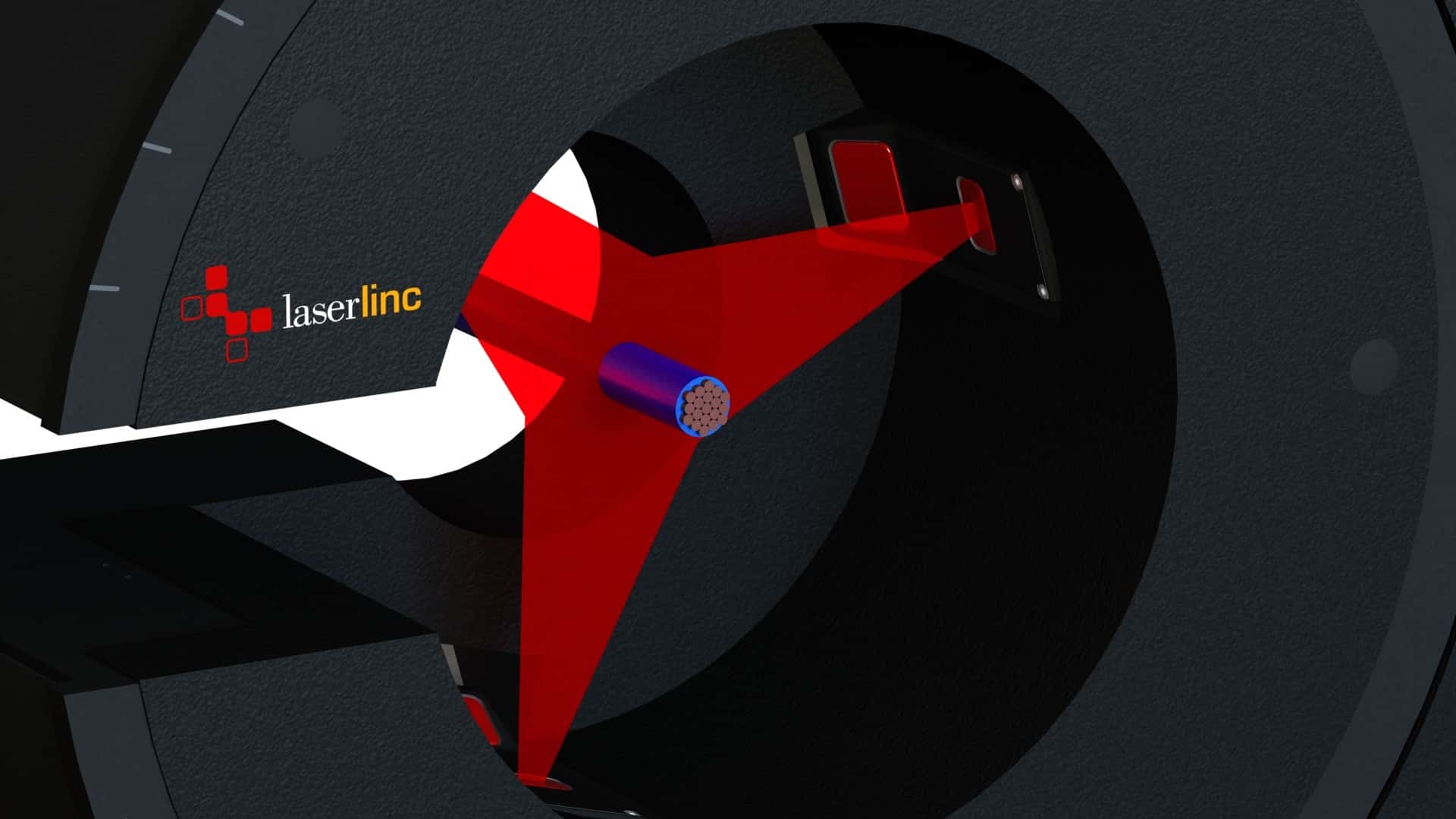
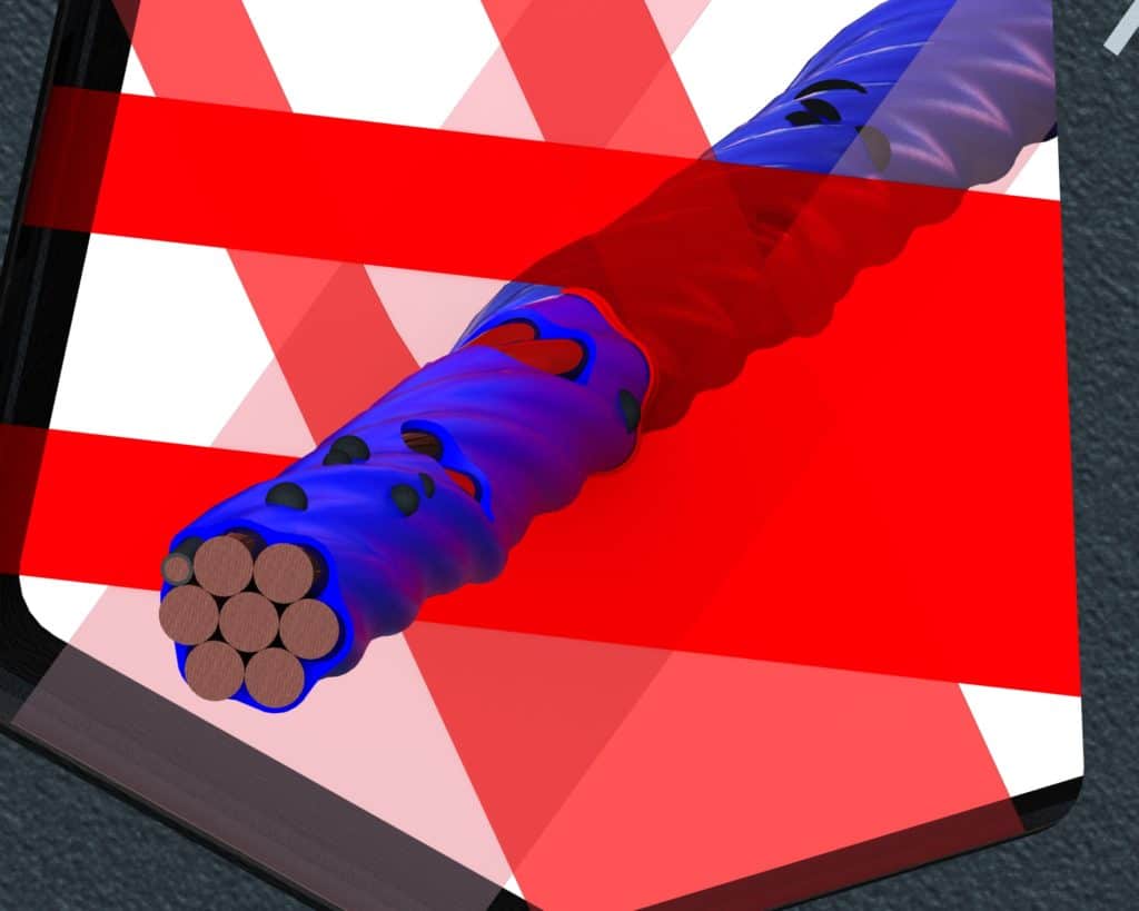
 Dual-axis laser micrometers check for out-of-tolerance and short-duration dimensional deviations. Dual-axis measurement can find defects even when they do not encircle the product.
  Single-axis laser micrometers check for out-of-tolerance or short-duration dimensional deviations, from just one direction. If the defects to catch always encircle a round product, a single-axis micrometer is appropriate.
 Six-axis detection of out-of-tolerance and short-duration dimensional deviations is done using two triple-axis micrometers mounted face-to-face for a total of six axes of inspection. This approach increases coverage and reduces blind spots.


